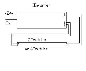
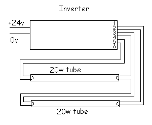
Inverter Installation Schematics
Case of Single Tube (either 20w or 40w)
Case of 2 x 20w tubes
The fluorescent tube setup, when inverter driven, does not require a starter switch as you find with mains installations. The inverter powers the heater filaments at either end of the tube until the tube strikes. When the inverter "sees" current flowing through the tube, the filament supply is switched off automatically.
Failure of installations is usually due to tube failure, although occasionally an inverter ceases to function. Tube failure can be confirmed by substitution, of course. It is useful to be able to confirm tube failure before first taking the (sometimes lenghty) walk to get a replacement tube. The filaments can be easily checked with a multimeter. The filaments should have a resistance of a few ohms (up to 30 in some cases). Any tubes with open circuit filaments at either end should be replaced as they are very unlikely to operate.
Experience has also taught us that lighting circuits which blow coach fuses almost always have problems with insulation. This usually occurs near the inverter where the input 24v supply "flying" lead has been rubbing against something metallic. The other problem which can cause fuses to blow commonly is filament lamps with loose glass bulbs. The two wires from the filament to the base contacts can become shorted together if the loose glass bulb is twisted round far enough.