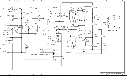
The circuit diagram of the PA transmitter unit is shown below. The unit is usually sited in the guard's compartment and is conveniently wired to the lighting control panel where the +24v and the two RCH cables are located.

The signal from the mouthpiece is amplified by Q1 by approximately x6. When the push to talk switch
is pressed the "transmitting" lamp comes on and RLA and RLB are closed. RLA then routes the signal
from Q1 pin 6 to the power amplifier which has a gain of x27 determined by R14 and R12. RLB is used to
disconnect the local guard's loudspeaker (if fitted) to prevent acoustic feedback.
The output signal from the power amplifier is passed through C13 to remove the DC component, then
boosted by T1 to match the impedance between the RCH cables. Part of the output audio is routed
through R2 and C12 back to the handset earpiece.
A repair service for these units is available from GoToPCs - just email me (see Home page)