Spring 2025
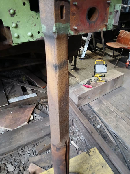
After completion of the initial chassis painting stages, the chassis metalwork was finished in gloss black. This is difficult to photograph, but see below! The area shown was exposed after removal of one of the vacuum brake cyinders. The vacuum reservoirs were also removed for cleaning up, painting and testing.
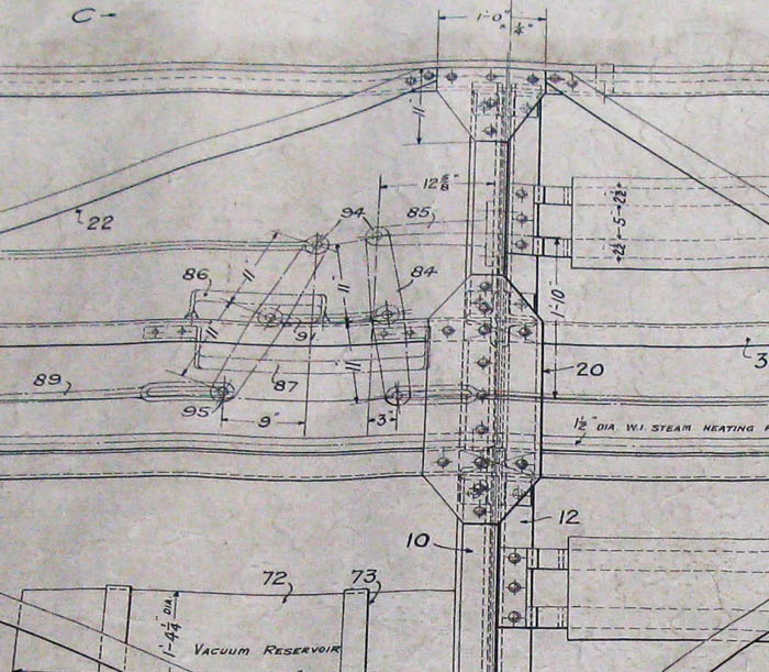
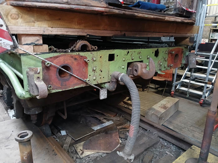
The brake rigging was the next thing to inspect. It turned out BR had modified the hand brake to operate on the west bogie only, as the tool racks they had installed prevented end to end brake rodding. We decided therefore to remove the tool racks from beneath the solebar and re-instate hand brake operation on both bogies. A drawing of the chassis and brake rigging was kindly supplied by our friends at the LNERCA to allow us to manufacture some of the missing parts.
To gain easy access to the tool racks, BR had bent the vacuum pipe upwards to clear the entry on the north side. After removal of the racks, the pipe was also cut so that it could follow the original Diagram 38 path along the lower edge of the north solebar.
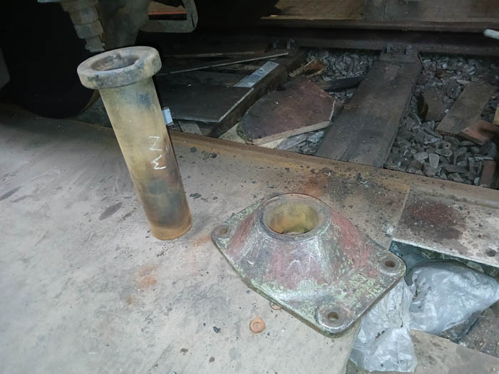
Some of the buffers were seized and the outer sleeve of the SW buffer came out rather further than it was meant to. We freed off and lubricated the east end buffers without too much trouble. The west end were a different story so we decided to remove and inspect both buffers, sleeves and castings. Much muck was removed from the sliding parts of the buffers which were then inspected. The SW buffer shaft was found to be very slightly bent and the NW one had some wear on the squared part of the shaft. The problem with the sleeve on the SW buffer was found to be a missing retention collet. Using the NW one as a pattern, a replacement was made by these nice guys in the steam shed.
It was observed that the drawhook at the west end was bent and misshapen, probably due to rough
handling when chains etc were slung over it to pull derailed vehicles out of the long grass (so to speak). Removing
and re-fitting drawhooks was a very steep learning curve. Not only was the pin which retains the drawhook to its
holding stud very difficult to remove, but getting the drawhook out past the two centring sprung pistons took a
lot of "blue language". We swapped the bent drawhook for a straight one removed from another vehicle.
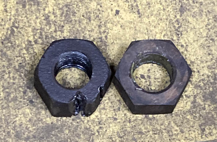
Then the fun and games really started - trying to remove the nut which held the hook retaining stud in the chassis.
This nut was a 2" BSW (Whitworth) and was very well rusted on. Eventually we found a second nut so decided to break the original
off the stud. Lots of drilling and cold chiselling later, the nut eventually started to move and was taken off.
This was necessary to releave the tension in the stud so it could be moved outwards several millimetres to allow
for re-fitting of the drawhook pin.